


Spindle System Start Here: Phase 1, Wiring First
Welcome to the start of your spindle system installation. One of the biggest advantages of a PwnCNC Spindle System is that the enclosed VFD makes the setup much more plug-and-play than a spindle kit. Instead of opening the VFD and landing wires on internal terminals, Phase 1 is simply about making the two core power connections needed to prepare the system for operation: plugging in the AC power cord and connecting the spindle motor power cable. By keeping this first step simple, you can get your spindle system physically connected and ready for manual testing before moving on to operation and any future controller integration.
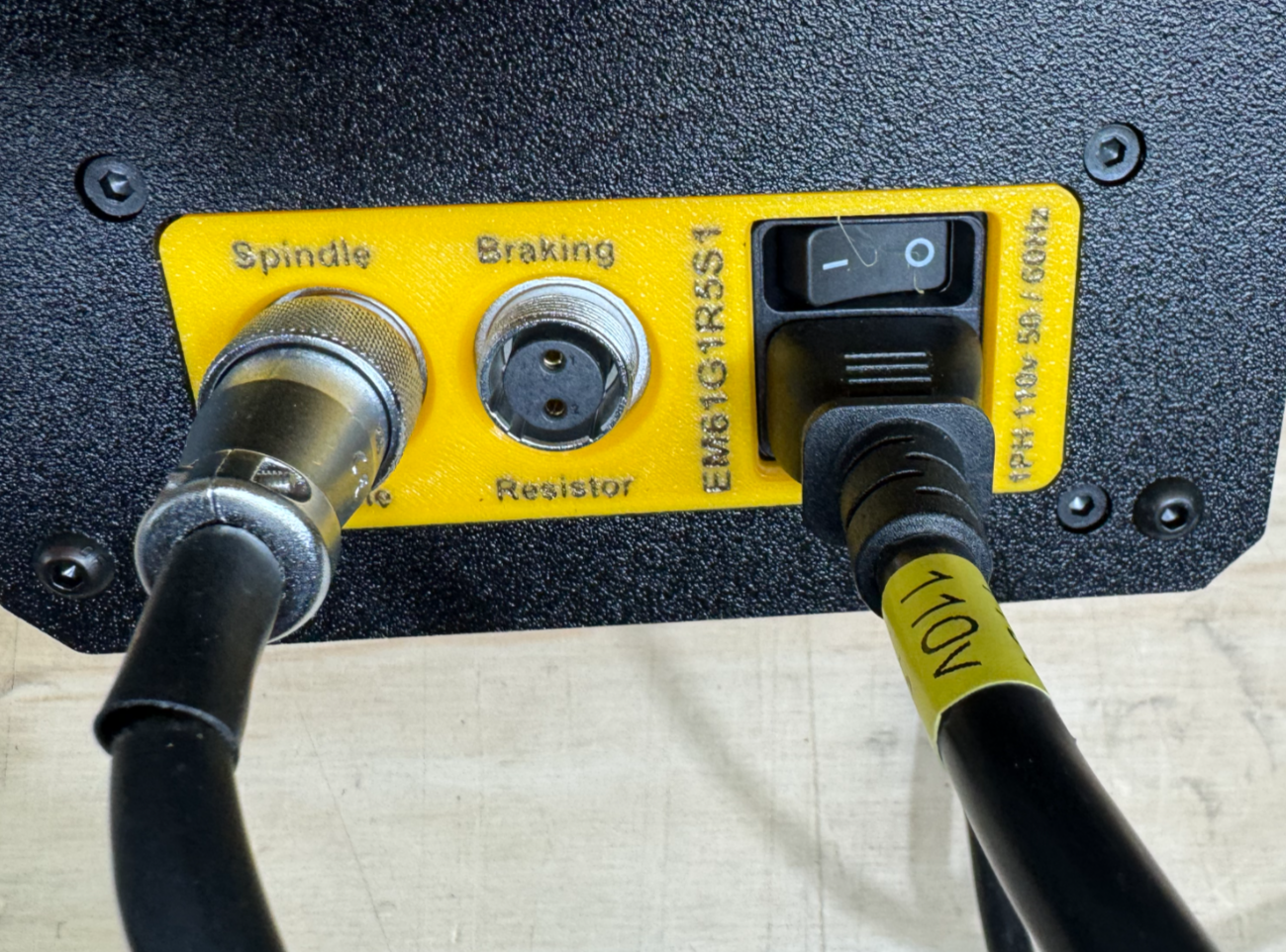
Unlike a spindle kit, where you wire directly into the VFD’s internal terminals, the spindle system is designed so these connections happen externally on the enclosure. The AC power cord uses a C13 plug that inserts into the power inlet on the right side of the VFD enclosure, and the spindle motor power cable uses a WS16 circular aircraft connector that also plugs into the right side of the enclosure. Once these two connections are made, the spindle system is wired for the next phase.
What this page covers
This article covers the minimum required wiring connections for your spindle system:
-
connecting the AC power cord to the VFD enclosure
-
connecting the spindle motor power cable to the VFD enclosure
This page does not cover manual operation, controller wiring, or automatic control. Those steps come later in the installation process.
Why this phase is first
We recommend completing the spindle system installation in phases so you can build confidence one step at a time. In this first phase, you are only making the basic plug-in connections required to prepare the system for use. That gives you a clear and simple starting point before moving on to Phase 2 - Manual Mode Operation, where you will power on the VFD and verify spindle function.
Before you begin
Before making any connections, make sure:
-
the spindle motor is physically installed in your machine
-
the VFD enclosure is positioned somewhere with access to AC power
-
the system is unplugged while you are making connections
-
the spindle motor cable is routed through cable chains so it has enough slack for full machine movement
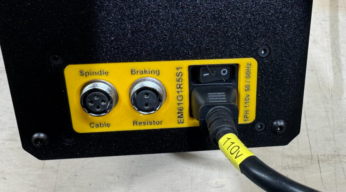
Step 1: Connect the AC power cord
Locate the included AC power cord and the power inlet on the right side of the VFD enclosure. Insert the C13 plug firmly into the enclosure’s power inlet until it is fully seated.
This is the power connection that feeds the VFD enclosure.
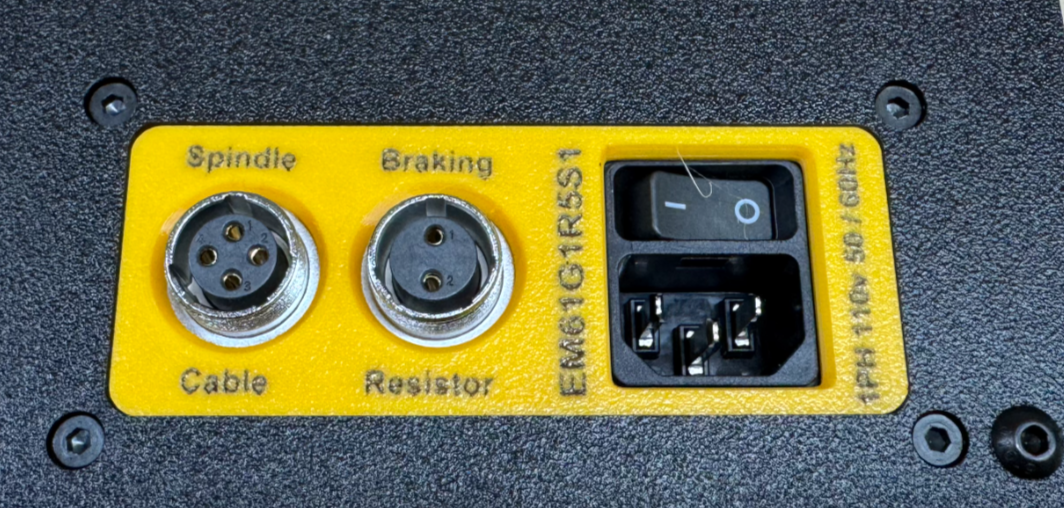
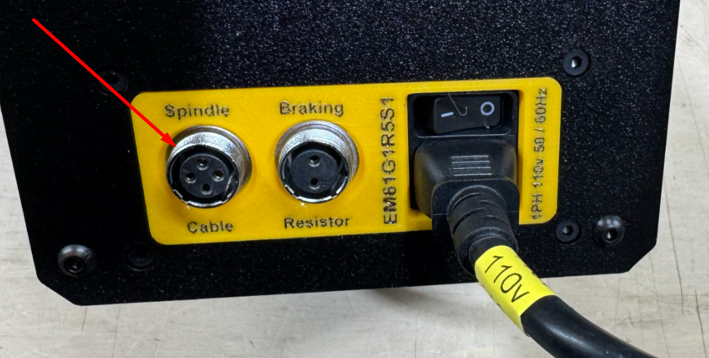
Step 2: Connect the spindle motor power cable
Locate the spindle motor power cable and the spindle port on the right side of the VFD enclosure. On spindle systems, this cable connects externally using the circular aircraft-style connector.
Align the connector properly, then insert the WS16 circular aircraft connector into the spindle port and tighten the retaining collar securely.
This cable carries power from the VFD enclosure to the spindle motor.
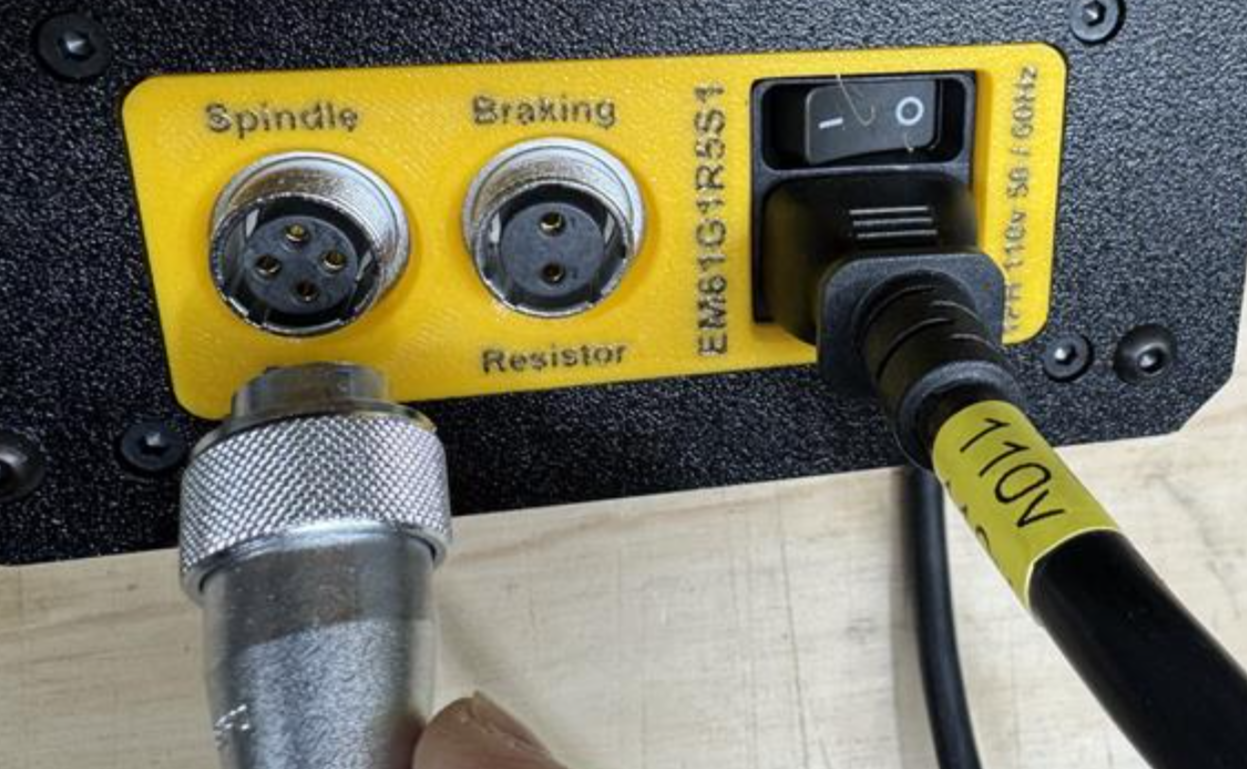
Step 3: Verify both connections
Before moving to the next phase, double-check that:
-
the C13 power cord is fully seated in the power inlet
-
the WS16 spindle cable connector is fully inserted and tightened
-
the cable routing allows for machine travel without pulling on the connectors
This is a good time to make sure your spindle cable is supported well enough that it will not be dragged, snagged, or pulled loose during machine movement. Spindle wires should be secured properly so they do not get dragged around the machine and become disconnected or damaged.
That’s it for Phase 1
Phase 1 for a spindle system is intentionally simple. Because the VFD is enclosed and pre-wired, there is no need to open the enclosure or land wires on internal terminals like there is with a spindle kit. Once the AC power cord and spindle motor cable are connected, your spindle system is wired and ready for the next step.
Next step
Continue to Phase 2 - Manual Mode Operation, where you will:
-
power on the VFD enclosure
-
verify the keypad lights up
-
place the system in manual mode
-
and confirm the spindle starts and stops correctly

