


Now that your spindle system is physically installed and the main wiring connections are complete, it is time for the next phase: learning how to operate your spindle in manual mode.
One of the advantages of the PwnCNC Spindle System is that it does not have to be locked into only manual mode or only automatic mode. Instead, the enclosed VFD includes a Manual Override Switch, also called the MOS, which allows you to switch between operating modes with a simple flip of a switch. This makes the spindle system more flexible than a spindle kit and gives you an easy way to run the spindle manually whenever needed. The MOS can be found on the left side of the VFD enclosure.
In this phase, you will use the MOS to place the spindle system into manual mode, then operate the spindle directly from the VFD keypad using the RUN, STOP/RESET, and speed dial controls. This is the easiest way to verify that your spindle system is installed correctly and functioning as expected before moving into automatic controller control later. This is the normal basic operating method before controller-based automatic control is used.
What manual mode means on a spindle system
On a spindle system, manual mode means the VFD itself is controlling the spindle. In this mode, you will:
-
power on the VFD enclosure
-
flip the Manual Override Switch into manual mode
-
use the keypad to start and stop the spindle
-
use the dial to adjust spindle speed
Unlike the spindle kit, the spindle system does not require reprogramming the VFD to move between manual and automatic operation. Instead, that change happens using the physical MOS switch built into the enclosure. Flipping the MOS upward / I / Manual allows RPM control from the VFD's keypad dial, while automatic control is used when the switch is not in that position.
Understanding the Manual Override Switch
The Manual Override Switch, or MOS, is located on the left side of the VFD enclosure.
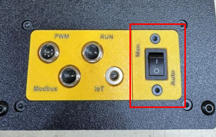
For spindle systems:
-
Switch down, or 0 = Automatic Mode
-
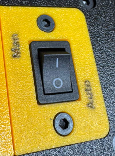
Switch up, or 1 = Manual Mode
When the switch is in the up / 1 position, the spindle can be controlled directly from the VFD keypad. That means the RUN button starts the spindle, the STOP/RESET button stops it, and the dial adjusts spindle speed.
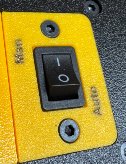
When the switch is in the down / 0 position, the system is set up for automatic control from the CNC controller instead.
Before you begin
Before powering on the spindle system, make sure:
-
the spindle motor is fully mounted in your CNC machine
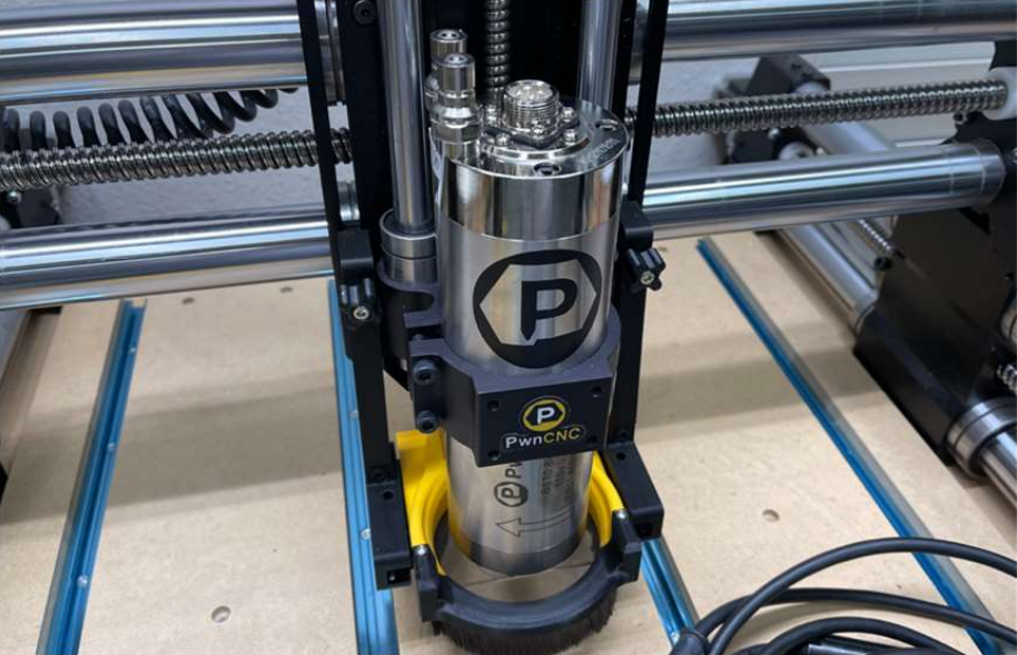
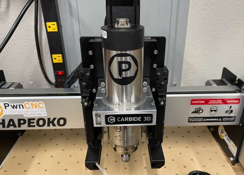
-
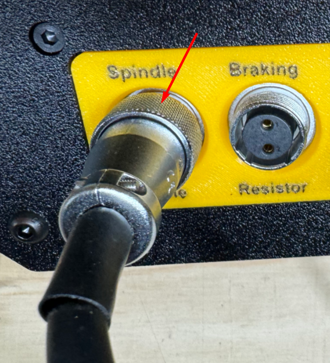
the spindle cable is connected to the spindle and the enclosure
-
the VFD enclosure AC power cable is plugged in correctly
-
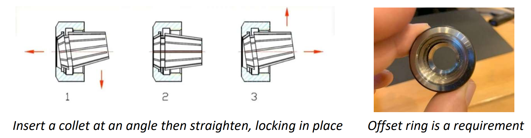
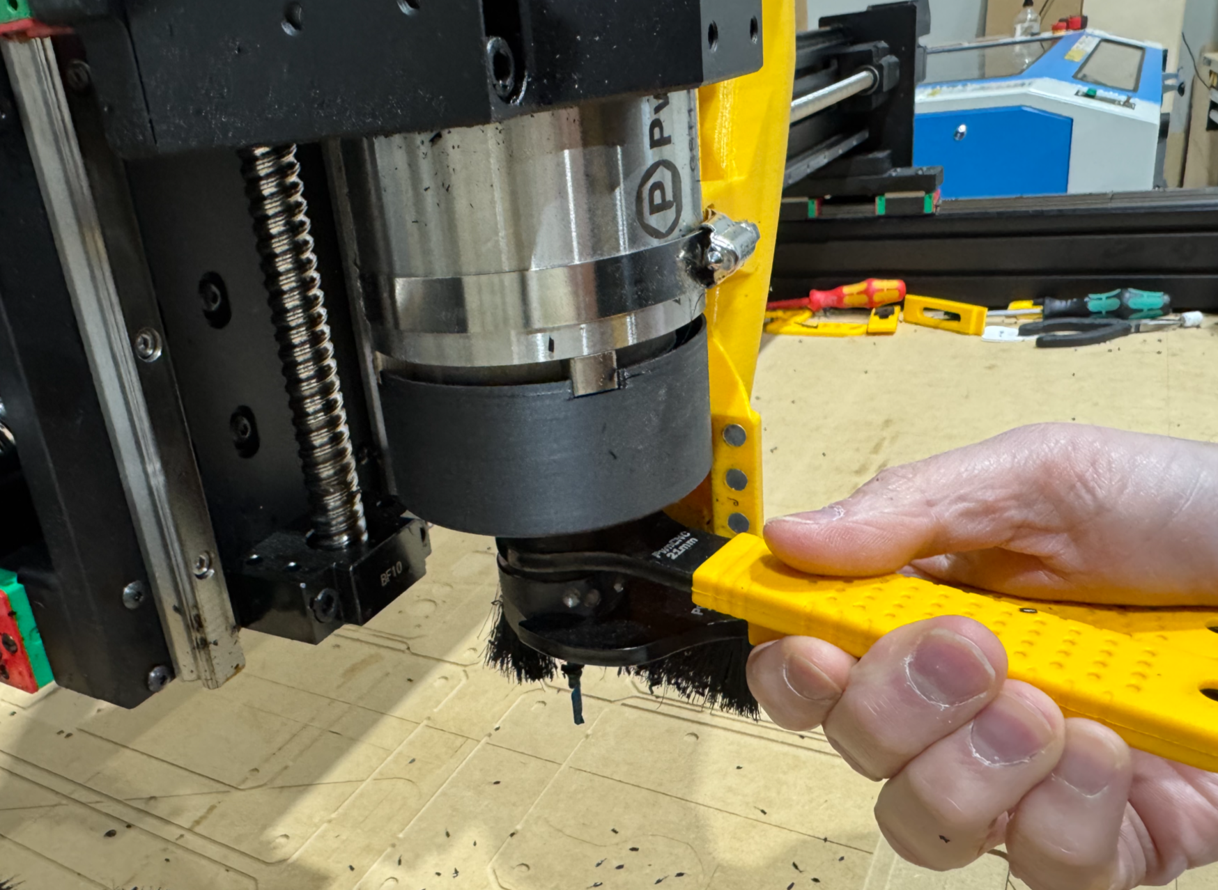
a bit is installed securely before running the spindle
-
if water-cooled, your coolant setup is ready
The spindle cable should be installed before powering up, and we recommend installing and tightening a bit using the included wrenches.
Powering on the spindle system
To power on the spindle system:
-
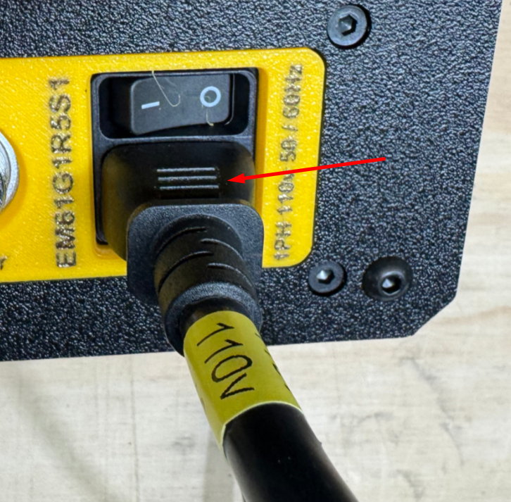
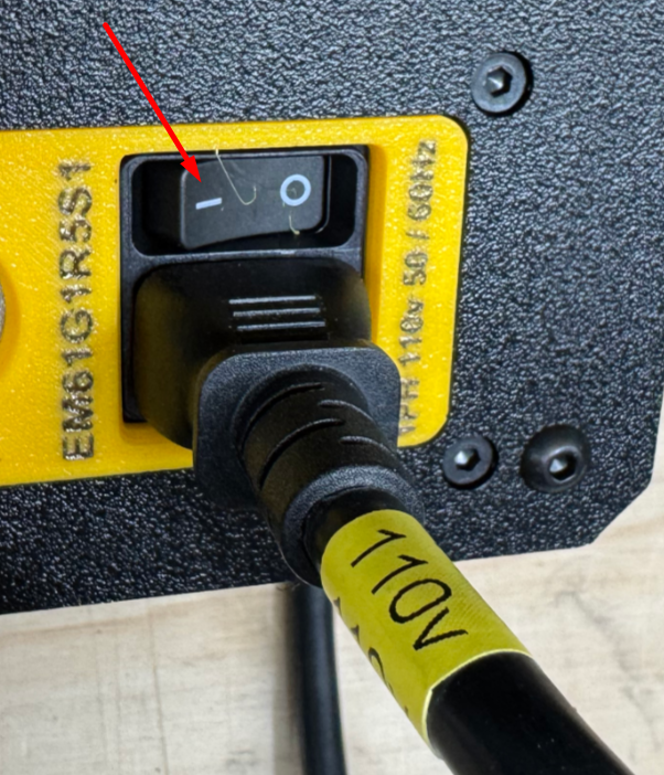
Plug the enclosure power cord into the correct AC outlet for your system.
(110v vs 220v: https://support.pwncnc.com/kb/article/641-power-requirements-110v-220v/) -
Turn on the power switch at the enclosure power entry.
-
Wait for the VFD keypad to light up.
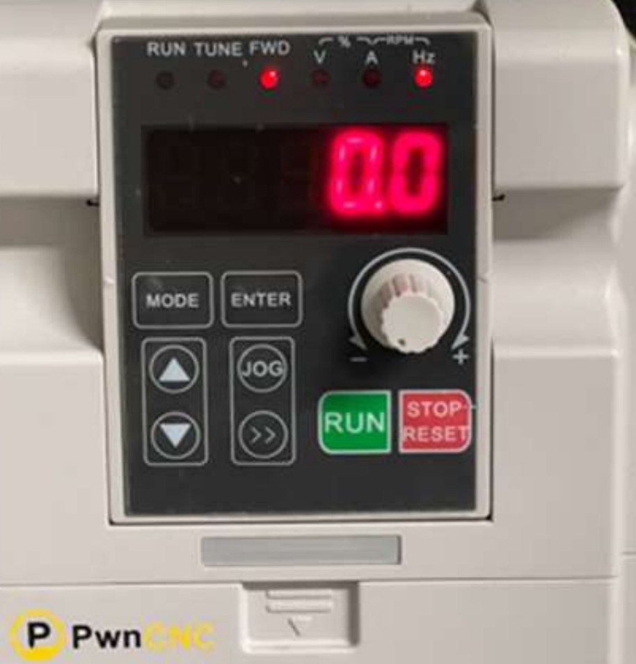
Once powered, the keypad should display red numbers or letters. In standby, the display should be blinking. Blinking indicates that the VFD is powered on, but the spindle is not currently running. The spindle system manual describes this exact behavior during initial power-up.

If the keypad does not light up, stop here and re-check your AC power source and enclosure power connection before continuing.
Switching into manual mode
Before trying to run the spindle from the keypad, flip the Manual Override Switch into the up / 1 / Manual position.
This step is what gives the keypad control over the spindle.
With the MOS in manual mode:
-
the RUN button will start the spindle
-
the STOP/RESET button will stop the spindle
-
the dial will control speed
Without the MOS in the manual position, the keypad will not be acting as the primary control point.
Starting the spindle
To start the spindle in manual mode:
-
Confirm the keypad display is blinking
-
Confirm the MOS is in the up / 1 / Manual position
-
Turn the speed dial all the way counterclockwise first
-
Press the green RUN button
-
The display should change from blinking to solid
-
Slowly turn the dial clockwise to increase spindle speed
The green RUN button and the dial are the basic controls for manual operation. It also recommends starting from a low setting, then increasing speed gradually. The keypad's dial, or potentiometer, regulates frequency and that the FWD LED above the numbers is on when the inverter is in run status.
Stopping the spindle
To stop the spindle:
-
Press the red STOP/RESET button
-
Watch the display as the spindle slows down
-
Wait until the spindle has stopped fully
-
Confirm the display returns to blinking standby mode before reaching near the bit
Stopping the spindle is as simple as pressing the red button, and advises users to wait until the display shows stopped status before reaching near the bit area.
Understanding the keypad
For many customers, this may be the first time using a VFD, so it helps to understand what the keypad is showing you.
The keypad provides two main kinds of information:
-
whether the VFD is running or stopped
-
what value is currently being displayed
According to the keypad reference page, the top indicator lamps show operating status and display units. These include indicators for forward operation, run status, voltage, current, Hz, and RPM-related display values. The keypad also includes the RUN button ![]() , STOP/RESET button
, STOP/RESET button ![]() , the speed control dial
, the speed control dial  , and the right-arrow style key used to scroll through monitoring values
 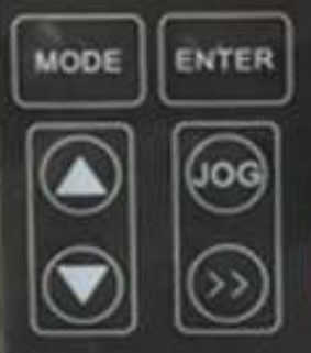 .
.
Blinking vs solid display
The simplest way to understand the display is:
-
Blinking display = powered on, stopped, standby mode
-
Solid display = spindle is actively running
What the numbers mean
When the VFD is blinking, it will most commonly be showing the current speed setting in Hz, which is the frequency the VFD will send to the spindle when started. The VFD’s base operation is frequency control in Hz, and that higher Hz means higher motor speed. It also notes that PwnCNC programmed the VFD so the display when running can show equivalent RPM values as well.
When the spindle is running, the display will typically show RPM, since that is more intuitive for most users. If needed, the double right arrow button can be pressed to cycle through available display values, including Hz or RPM while running.
Simple first test
A good first manual mode test for a spindle system is:
-
Power on the enclosure
-
Confirm the keypad lights up and is blinking
-
Flip the MOS to up / 1 / Manual
-
Turn the dial fully counterclockwise
-
Press RUN
-
Slowly increase speed with the dial until the spindle begins spinning
-
Confirm the display becomes solid while running
-
Press STOP/RESET
-
Confirm the spindle stops and the display returns to blinking
A note about Hz and RPM
VFDs naturally control motors by output frequency, not directly by RPM. That is why Hz is a normal thing to see on the keypad. PwnCNC has programmed the VFD so customers can also view RPM, which is usually easier to understand during spindle operation. For reference our spindle motors are typically 0-400Hz or 24,000 RPM... thus a value of 200 Hz corresponds to 12,000 RPM on this programmed setup, and that the display can be cycled between values using the keypad.
Warm-up reminder
We recommend a spindle warm-up procedure, especially after long downtime or in cold conditions. We suggest beginning at a lower RPM, then gradually stepping up speed over time to allow the spindle bearings and lubricant to come up to operating condition.
What comes next
Once you have confirmed that:
-
the enclosure powers on
-
the keypad blinks in standby
-
the MOS correctly switches the system into manual mode
-
the spindle starts when you press RUN
-
the display turns solid while running
-
the dial changes spindle speed
-
and STOP/RESET returns the system to blinking standby
then your spindle system is successfully operating in manual mode.
From there, the next step is automatic mode, where your CNC controller takes over spindle start, stop, and speed control. On a spindle system, switching between manual and automatic operation is much easier because the MOS gives you a direct way to change modes without needing to reprogram the VFD.

